Hey everyone! This blog covers the basics of computer networking. So let’s start with the fundamental question… Exactly what is a computer network? It’s a network of two or more two devices exchanging information and data. Let’s understand this statement with the working of multiple devices connected to a router.
Most of us have routers at our homes, and multiple devices (like laptops, smartphones and other devices) are connected to the network provided by ISP (Internet Service Provider). So what happens, ISP assigns an IP address to our router, let’s say 188.2.51.202. This is a global IP address that is unique and is what the outside world uses to identify and communicate with your home network. Our laptop has a local IP address like 192.168.254.11, while your smartphone might have 192.168.254.12, and so on. These are local IP addresses, used within your home network to communicate between devices.
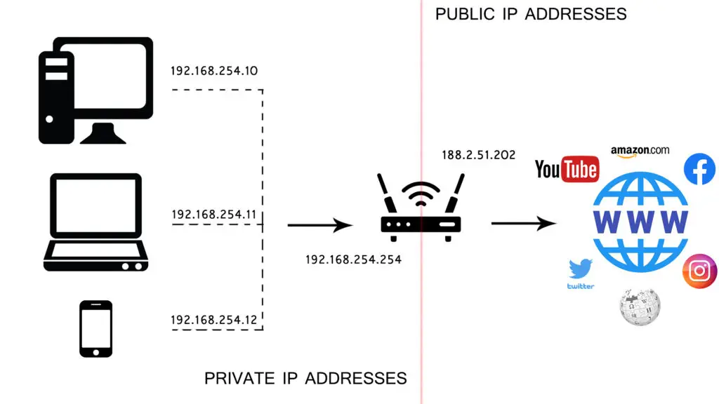
Now, our laptop wants to browse the internet. It sends a request, router will use NAT (Network Address Translation). It will replace the local IP of a laptop with the global IP of the router before sending the request to the internet.
Here, there is a very important protocol that plays crucial role in assigning local IP addresses to devices dynamically :- DHCP (Dynamic Host Configuration Protocol).
Let’s try to understand what IP address and what is the need for it. An IP address acts as a unique identifier for devices in a network, much like a street address pinpoints a particular building in a city. However, to ensure the data reaches the correct application or service on that device, we need something more specific. This is where ports come into play—they’re like room numbers or offices within that building. There are 2^16 ports ranging from 0 to 65535. Ports from 0 to 1023 are reserved. For e.g. port 80 is for HTTP, port 25 is for SMTP. We’ll talk about IP address and protocols in detail later.
OSI model
Till now, we have built a fundamental understanding of networking. Let’s dive bit deeper to know more about networking and its complexities. For this, we turn to OSI model (Open System Interconnection model).
OSI is a logical model for communication between systems. It was modeled first then protocols were implemented. It is composed of 7 layers, in which each layer is dependent on the layer above and the layer below.
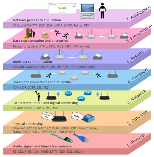
Application Layer
It is the topmost layer of the model that serves as an interface between the network and software running on the device. This layer is directly interacted with by users, and it hosts various protocols necessary for specific applications. Examples of application layer protocols include:
- Hypertext Transfer Protocol (HTTP): For viewing web pages and accessing web resources.
- Domain Name System (DNS): For quickly accessing web pages using names instead of IP addresses.
- File Transfer Protocol (FTP): For transferring computer files.
- Internet Message Access Protocol (IMAP): For accessing and storing email.
- Simple Mail Transfer Protocol (SMTP): For sending outgoing email.
Presentation Layer
It is the sixth layer of the model, responsible for the formatting and presentation of data. Its main functions include data translation, encryption and decryption for secure transmission, compression and decompression of data. It ensures that information sent from one system can be read by another system, regardless of differences in data representation.
Session Layer
This layer manages and controls the communication between devices. The session layer handles the connection and authentication between a client or server, including actions like logon, lookup, log off, or session termination. DNS, along with name resolution protocols, operate in the session layer. .
Transport Layer
It is the fourth layer of the OSI model. Transport layer uses protocols like TCP and UDP for data transfer. The functions of this layer include:
Segmentation and Reassembly The transport layer breaks down data from the session layer into smaller segments for smooth transmission across the network. It then reassembles these segments into the original message at the receiving end. Protocols like TCP, UDP have different sizes of segments.
Congestion control This situation occurs when too many sources attempt to send data over the network, which may result in overflowing router buffers, thus causing the loss of data packets. Transport layer uses mechanisms to control the rate of transmission to prevent congestion and ensure efficient data delivery. For example, the sender is sending data to the receiver at 20 Mbps, but the receiver is not able to process the data at the same rate, so it asks the server for a 3 Mbps rate. This is called congestion control.
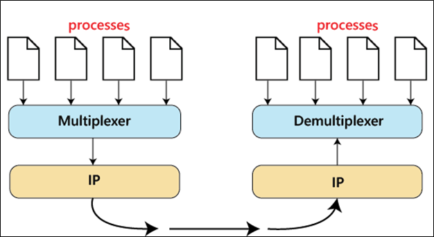
Multiplexing and Demultiplexing The transport layer allows multiple applications to use the network simultaneously by multiplexing data from these applications into a single stream for transmission. At the receiving end, it demultiplexes the received data and directs it to the appropriate application.
Errors checking and correction It performs error checking by adding sequence numbers, checksums, or other mechanisms to detect errors in the transmitted data.
Network Layer
This layer is mainly responsible for the logical transmission of data over the entire network. Its main functions include routing, forwarding, and addressing (for identifying devices over the internet).
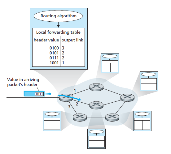
Routing Routing is the process of determining the best path for sending data from the source to the destination based on various metrics, such as hop count, bandwidth, delay, or cost.
Forwarding Forwarding involves the actual movement of packets from one router’s input interface to the appropriate output interface.
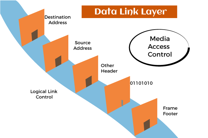
Data Link Layer
This layer divides packets received from the Network layer into frames and then sends them bit-by-bit to the physical layer. It is one of the most complex layers in the OSI model as it hides the complexities of the hardware. This layer also involves physical addressing, enabling the identification of the sender and receiver of frames on the network. Ethernet and Wi-Fi are examples of technologies that operate at the Data Link Layer.
Physical Layer
It is the lowest layer in the OSI model that deals with the physical connection between devices and the transmission of raw data bits over a physical medium. It transforms the digital bits received from the Data Link Layer into signals that can be transmitted over the physical medium.
Difference between Logical Addressing and Physical Addressing
Logical Addressing refers to addressing scheme used to uniquely identify devices within a network at Network Layer. Logical addresses are used for routing data across networks. For e.g. IP addresses in both IPv4 and IPv6 are examples of logical addresses.
Physical Addressing involves unique identification of devices within a network at Data Link layer. For e.g. MAC (Media Access Control) addresses in Ethernet networks and the physical addresses in networks like Wi-Fi are examples of physical addressing.
MAC address
It stands for Media Access Control, a unique identfier address during device manufacturing. MAC is represented as 12-digit hexadecimal number in colon:hexadecimal notation. Each network interface in a device has its own MAC address. For e.g. if a device has both ethernet and wifi, there will be two MAC addresses. MAC address looks like : 00:1A:4C:3B:9D:2E
In this article, we’ve covered the basics of computer networking, including the OSI model. We’ll explore protocols in later parts of this article to build on what we’ve learned.